Microcontroller State Machine Implementation
State machines are useful tools that in the right application can simplify designing microcontroller firmware. They allow you to create an event-driven system that can change its response to inputs based on its internal state. The example below introduces one way to structure a state machine in a microcontroller environment.
Consider an example system that contains a microcontroller connected to an LED and a push button. In this example system one press of the button turns on the LED, a second push of the button will make the LED blink, and if the button is pressed again the LED will turn off. Also, our system must turn off the LED after a period of inactivity. If the button hasn't been pressed in the last 10 seconds, the LED will turn off.
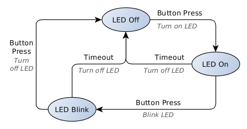
Figure 1: Example system state diagram
In our example, every time the button is pressed, the system must take one of three possible actions (turn on the LED, blink the LED, or turn off the LED). The response to a button press depends on the current status of the LED, which can be affected by another event in the system (the 10-second timeout). We must therefore create a system that keeps track of the LED and uses its status to decide what to do in response to an input.
A state machine will generate an output determined by both the current internal state of the system and the input it receives. By changing the state, the system can generate a different output given the same input as before. If we use the states to keep track of the LED, then we can determine which output to generate when the button is pressed.
State Machine Structure
For microcontroller applications, let's use the definition of a finite-state machine. A finite-state machine has a known set of inputs, outputs, and states. The state diagram in Figure 1 contains all the elements we need to describe our state machine; let's define the four different elements of a state machine.
Inputs—any event that requires our system to generate an output or change its behaviour is an input. Our example has two inputs: a 10-second timeout and a button press. In our state diagram, the inputs are listed above the arrows connecting the states.
State transitions—the arrows in the state diagram represent state transitions. These define when our system will change its behaviour by changing its internal state. State transitions can only be triggered by an input. In our example, we trigger a state transition every time an input produces an output that changes the status of the LED. This way the system's state always keeps track of the LED. The state transitions also define how our system is allowed to change behaviour. For example, there is no arrow connecting the LED off state and LED blink state, therefore the LED can never change directly from the off state to the blink state.
Outputs—actions that need to be taken by the system in response to an input are outputs. In Figure 1, the outputs are listed in italics under the state transition arrows. Like state transitions, our system can only generate an output following an input event. Our system has three outputs: making the LED turn on, blink or turn off.
States—the circles in the state diagram represent the states. A state is a list of rules that tells the system what to do when an input event occurs. When an input occurs, the system will look at the set of rules defined in its current internal state and look up which output or state transition it needs to generate, or whether it should do nothing at all in response to the input. Our states are the three different LED behaviours we outlined earlier; the state machine is only allowed to exist in one of these states.
But how do we decide what our states will be, or even how many we should have? Each state is a different set of rules that define how the system will respond to the inputs, so all the states need to cover the different output behaviours we need. Let's take a look at the input-output relationships of our example in a table instead of the state diagram above.
| State | Input | Output |
|---|---|---|
| LED Off | Timeout | None |
| LED On / LED Blink | Timeout | Turn off LED |
| LED Off | Button Press | Turn on LED |
| LED On | Button Press | Start blinking LED |
| LED Blink | Button Press | Turn off LED |
The button press input can produce three possible outputs based on our example description. Because the output is dependent on the state and the input, the only way one input is allowed to produce three possible outputs is to have three states. A timeout event results in two possible actions, but these can be included in our three other states.
Finally, it's important to define the initial state of our system. This is the state that the system will start in on power-up, or if a reset occurs. Our state machine will always start in the LED off state.
The Hardware
Before we implement the different elements of our state machine in code, let's look at the hardware we'll use.
The example hardware can be put together with an Arduino, a momentary switch and a capacitor to debounce the switch. The switch is connected across the digital 2 and 4 pins on the Arduino (PD2/INT0 and PD4, respectively on the Atmega) with a suitable valued debounce capacitor (100nF) in parallel. Pin 4 is set as a sink and pin 2 is set up as an input with internal pull-up enabled. The example also uses the on-board LED connected to pin 13 (PB5/SCK on the Atmega).
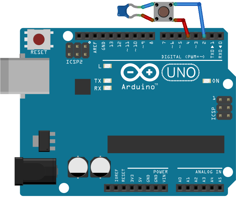
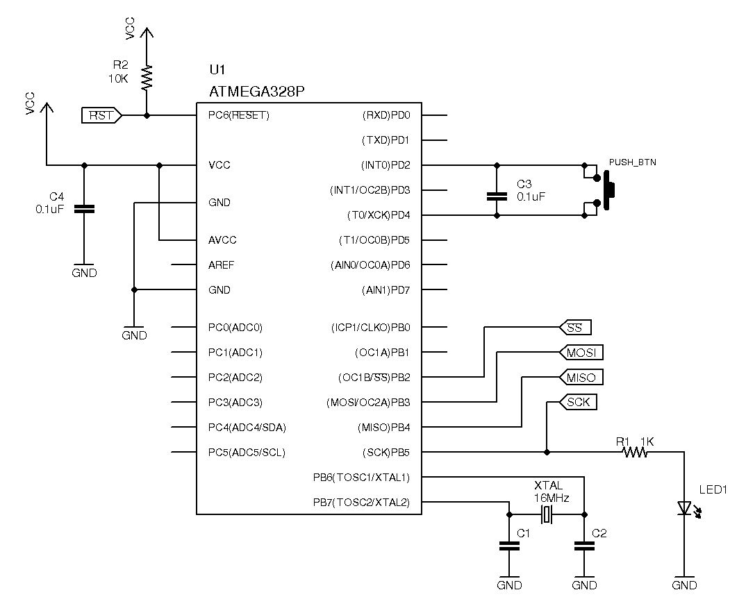
Figure 2: Hardware used to implement our example (click on an image to enlarge)
Alternatively, the example hardware can be built on a breadboard. The schematic on the right shows the relevant Atmega328 circuit used in this example.
Programming a State Machine
Based on our definitions of a state machine, we need to program each state as a list of instructions to execute (outputs, state transitions) for each possible input, and then have the code navigate to the correct set of instructions. One simple way to do this is to use nested switch statements as shown below.
/*  Example of nested switch statements     */

switch(system_state){
    case led_off:
        switch(system_input){
            case button_press:
                turn the led on;        // Output
                system_state = led_on;  // State transition
                break;
            case timeout:
                break;                  // do nothing
        }
        break;
    case led_on:
        switch(system_input){
            case button_press:
                blink the led;              // Output
                system_state = led_blink;   // State transition
                break;
            case timeout:
                turn off the led;           // Output
                system_state = led_off;     // State transition
                break;
        }
        break;
    case led_blink:
        switch(system_input){
            case button_press:
                turn off led;           // Output
                system_state = led_off; // State transition
                break;
            case timeout:
                turn off led;           // Output
                system_state = led_off; // State transition
                break;
        }
        break;
}
Example code: Using nested switch statements to generate an output
The system_state variable is used to keep track of the current state of our system. The outer switch statement directs the program to the correct set of rules to use, and the inner switch statement tells the program which instructions to execute.
This is a suitable implementation for a simple system (like the LED example above). However, it becomes difficult to maintain this code once the system is scaled to have many possible events and states.
Because each state's behaviour is independent of the other states, there's no need to group them all up in the switch(system_state) statement above. We can instead encapsulate each state as its own function that only contains the information relevant to that state. The code below shows how this is implemented in the example program.
/*  State Input Handler Functions   */

void LEDoff(TInputs next_input){
    switch(next_input){
        case IN_BTN_PRESS:      /* LED Off + Button Press */
            LED_ON();                       /* Output */
            led_timeout_start();            /* start the timer */
            sm_led.currentState = LEDon;    /* State Transition */
            break;
        default:
            break;
    }
}

void LEDon(TInputs next_input){
    switch(next_input){
        case IN_BTN_PRESS:      /* LED On + Button Press */
            led_timeout_start();            /* reset the timer */
            LED_BLINK_START();              /* Output */
            sm_led.currentState = LEDblink; /* State Transition */
            break;
        case IN_TIMEOUT:        /* LED On + Timeout */
            LED_OFF();                      /* Output */
            sm_led.currentState = LEDoff;   /* State Transition */
            break;
        default:
            break;
    }
}

void LEDblink(TInputs next_input){
    switch(next_input){
        case IN_BTN_PRESS:      /* LED Blink + Button Press */
        case IN_TIMEOUT:        /* LED Blink + Timeout */
            LED_BLINK_STOP();               /* Output - step 1 */
            LED_OFF();                      /* Output - step 2 */
            sm_led.currentState = LEDoff;   /* State Transition */
            break;
        default:
            break;
    }
}
Code Excerpt 1: Implementing each state as a separate function
The above code introduces how our state machine will run. Instead of the outer switch statement, our code will call the current state's function each time an input occurs. Inside the state function, the code decides what output and state transition need to occur based on the input provided in the next_input variable.
Here we also see that output and state transition instructions are placed under their input cases in the switch statements.
To better understand the state functions, let's look at how we implement the other elements of our state machine.
/*  State Machine Structure     */

#define IN_QUEUE_SIZE     32

/*  all the possible inputs of our state machine */
typedef enum{
    IN_NONE    = 0,     /* No Input */
    IN_BTN_PRESS,       /* Button Press */
    IN_TIMEOUT          /* Timeout */
} TInputs;

/*  the parts will be stored in the TStateMachine type  */
typedef struct StateMachine TStateMachine;

/*  pStateHandler is a pointer to the state functions. */
typedef void ( *pStateHandler )(TInputs next_input);

/*  function prototypes of the states */
void LEDoff(TInputs next_input);
void LEDon(TInputs next_input);
void LEDblink(TInputs next_input);

/*  here is the state machine structure. */
struct StateMachine{
    pStateHandler           currentState;
    volatile TInputs        inQueue[IN_QUEUE_SIZE];
    volatile uint8_t        queueCount;
    uint8_t                 queuePos;
};

/*  declaration of the LED state machine */
TStateMachine sm_led =  {   .currentState = LEDoff,
                            .queueCount = 0,
                            .queuePos = 0
                        };
Code Excerpt 2: Initializing our state machine variables
Our set of inputs is listed on line 48 as an enumerated type we will call TInputs. When an input occurs, we store it in the buffer inQueue[]. The variables queueCount and queuePos will be used to keep track of our input buffer.
We list the state function prototypes on line 61. Each state function takes the same argument – one of the inputs from our enumerated list. We can then create the pointer currentState, which can point to any of these functions.
The variable currentState is a pointer to the state function that matches our current system state. We can use it to keep track of the system state and execute the current state function by calling currentState(). State transitions are achieved by changing the pointer to one of the other state functions. The initial state is set to LEDoff on line 74.
We group the variables needed to run our state machine together in the StateMachine struct and initialize our state machine sm_led.
Next let's look at how our example receives inputs. As mentioned before, the inputs are stored in the sm_led.inQueue[] buffer in the order they occur. The buffer keeps track of the inputs in case they occur faster than we can can process them. All of the inputs to our system can be obtained using the microcontroller interrupts. This makes our job much easier. Hardware interrupts occur asynchronously and ensure that the inputs get processed in the order they occur. We can just let our state machine run or sit idle while the interrupt service routines add our inputs to the buffer.
The simple circular buffer code below quickly adds input information to the buffer using the QueueInput() routine and retrieves it when we are ready to process an input using the GetNextInput() routine. It also shows how our button press interrupt routine uses QueueInput().
/*  add an input flag, in_f, to the input queue of sm */
void QueueInput(TStateMachine *sm, TInputs in_f){
    uint8_t i;
    //make sure the input queue is not full
    if(sm->queueCount < IN_QUEUE_SIZE){
        i = sm->queuePos + sm->queueCount;
        i %= IN_QUEUE_SIZE;
        sm->inQueue[i] = in_f;
        sm->queueCount++;
    }
    return;
}

/*  return the next input event from the input buffer of sm */
TInputs GetNextInput(TStateMachine *sm){
    TInputs next_input;
    if(sm->queueCount == 0){
        // Input queue is empty
        next_input = IN_NONE;
    }
    else{
        next_input = sm->inQueue[sm->queuePos];
        sm->queuePos++;
        if(sm->queuePos == IN_QUEUE_SIZE)
            sm->queuePos = 0;
        sm->queueCount--;
    }
    return next_input;
}

/*  Interrupt routine for button press  */
ISR(INT0_vect){
    QueueInput(&sm_led, IN_BTN_PRESS);
}
Code Excerpt 3: Adding inputs to the inQueue[ ] buffer
Now we can simply run our state machine.
int main(void){

    systemInit();   /* set up the system */

    for(;;){        /* loop forever */
        if(sm_led.queueCount){
            (sm_led.currentState)(GetNextInput(&sm_led));
        }
    }
}
Code Excerpt 4: The main() loop
Line 117 checks if there are any inputs in the queue. Line 118 calls the current state function and passes it the next input. As long as there is an input in the queue, the current state function is called to process the input. For example, if the state machine is in the LED off state and the next input to be processed is a button press, line 118 is the same as calling LEDoff(IN_BTN_PRESS);
Full code for avr-gcc here: main.c
Design Considerations
Latency—When using interrupt routines, best practice is to keep them as short as possible. Limit ISR function to adding the input event to the queue and let the state functions handle lengthy computations. This ensures input events are queued and processed in the order they occur by the state functions, and that behaviour is predictable.
However, this can lead to longer than required delays between an input occurring and an output being generated. If an input is added to the buffer behind a couple of other pending inputs whose output functions are lengthy, it will sit in the queue until the other inputs are processed. If an input requires the system to take action immediately, consider reacting to it outside of the state machine. It is often unacceptable for an emergency stop signal to be queued in the input buffer behind some less critical input events.
Another way to ensure important events are handled first is to add priority levels to the input events. The system can add the input events to two or more separate buffers based on the priority level of that input. When the main loop checks if there are any pending inputs to be handled, the highest priority input buffers are cleared first before checking subsequent ones. The trade-off is that we lose some predictability in the system because the inputs are no longer handled in the order they occur, but we ensure important inputs are handled in a timely manner.
Sleep modes—Because most microcontrollers can be put in a low-power mode and wake from interrupt, this implementation can work well in low-power systems. The system can be put in a sleep mode when no more inputs remain in the queue. Triggering an interrupt from input sources allows the system to wake when a new input occurs. When choosing the input sources for your microcontroller, consider which ones can wake it from the desired low-power mode.
Advantages of Using a State Machine
The code structure we have outlined in our example is an alternative to using one big loop and polling inputs in event-driven microcontroller applications. But the state machine gives us more benefits than just avoiding the superloop full of spaghetti code.
The state machine definition given previously allows us divide the code into structured parts. Once the system is defined, writing the code is simple. All of the states, inputs, outputs and state transitions are known, and it's just a matter of putting them in the software template above. Testing the code even becomes easier; run through every possible state-input pair and check that the outputs and state transitions behave as intended.
The program structure above is easy to scale to a system with many inputs and states. Adding more states is as simple as adding another state function; adding more inputs requires adding another case to the switch statements. In a real system, outputs and state transitions may be more complicated than a few lines of code, but these can be grouped into their own functions to keep the state functions tidy. The state functions are easily read and maintained if these are split into functions such as exitStateA();, enterStateB();, ouputB1();, outputB2();.
Many microcontroller applications involve an event-driven component in the system. State machines offer an easy way to manage these systems as a whole or as a sub-system within a program. A user interface or a string parser implemented as a state machine will happily coexist with other code in a system while it waits for an input event from another section of the program or an interrupt routine. Although using an event handler can often suffice without the need for switching states, the additional layer of a state machine can allow you to easily manage changes in behaviour within the system or even implement a diagnostic mode.